Flow Balance at Junctions
Because of the use of rational method hydrology, flow discontinuities may be noticed. This is a condition where the sum of the inflows does not equal the sum of the outflows. The main reason for this is that the rational method is only concerned with peak flows and has a high dependence on duration (system time). As the system time changes, the intensity changes and has a direct effect on the rate of flow in the system.
The most common cause of confusion with this discontinuity stems from rational loads that are tracked through a long piping system without any other loads entering the network. At the inlet of origin, the time of concentration may be relatively small, resulting in a high intensity and a large peak discharge. As the load travels through the pipes, the system time becomes larger, so the intensity lowers. This results in smaller discharge values, so the peak flow at the outlet may be significantly smaller than the peak flow at the original inlet.
This may seem counter-intuitive at first, with questions like "Where did the rest of the flow go?" coming to mind. In reality, the rest of the flow was not lost, but an attempt to balance peak flows is not valid. Picture standing at the top of a hill with a bucket of water. If you empty the entire bucket into the gutter in one second, then the peak rate of discharge at the top of the hill is one bucket per second. Racing to the bottom of the hill, you can observe the flow and see that the peak flow is much less than one bucket per second. However, the flow lasts longer than one second. There was no water lost, but the peak was lower.
Drainage and Utilities does not simply add flow at a junction node; rather, it takes into account the attenuation of peak flow as one moves downstream by keeping track of upstream catchment properties and decreasing the peak intensity according to the time of concentration and travel.
The flow out of a catchment is:

Where:
And the flow out of a junction is:
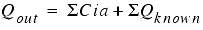
One would think therefore that flow in equals flow out. However, the intensity (i) used for determining the flow into the manhole will be higher than the intensity of the flow leaving the manhole.
This intensity is calculated using the longest possible flow travel time in order to generate the most conservative value for peak flow. For example, say a catchment empties into a catch basin and has a Time of Concentration of 10 minutes. On the other hand the travel time of the piped flow getting to the catch basin is 12 minutes. The rational flow generated at the catch basin will be generated based on the intensity associated with the 12 minute duration. This way you are assured that the whole system is contributing to the flow and hence you are using the most conservative peak flow value at that point.
If you do not wish to have this flow attenuation taken into account, you should specify Known or Additional flows at the catch basins.
See theSystem Time / Controlling Time / Duration topic for more information.